To measure pressure, piezoresistive strain gauges are frequently employed. They determine the pressure by monitoring the material’s electrical resistance as it is stretched.
These sensors are versatile due to their low cost and high durability. They are versatile enough to measure pressure in a wide range of conditions, from vacuum to high pressure.
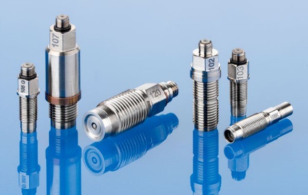
Function
Wheatstone bridge circuits are commonly used to measure the sensor’s change in resistance. This enables a voltage to be generated from variations in the sensor’s resistance, however slight.
Wheatstone bridge circuit is used to measure strain with a piezoresistive strain gauge. Bridge operation requires an excitation voltage. The output of a bridge with perfectly balanced resistors and no load is 0 volts. The resistances in the bridge will shift in response to a change in pressure, and the resulting voltage or current will be output.
Utilizing two or four different sensors in the bridge, with each pair of elements experiencing equal and opposite strain, can increase performance. This improves the signal output and helps reduce the impact of temperature on the sensor’s components. Follow the link https://www.kistler.com/en/glossary/term/piezoelectric-pressure-sensor/.
Metal-based sensitive components
A diaphragm can be outfitted with one or even more strain gauge sensors, each consisting of a short segment of wire.
If you put some weight on the diaphragm, the wires will stretch and the resistance will vary. As an alternative to adhesive bonding, the conductor can be sputtered directly onto the diaphragm, where the sensor parts can then be attached. The second approach simplifies the building of compact devices and eliminates issues that may arise from the adhesives’ failure at high temperatures.
To create a metal wire sensor, simply wind a wire around some posts that move in response to pressure. Given that no adhesive is used to secure the wire to the posts, this design is also functional in warmer environments.
Sensing components based on semiconductors
Strain gauge pressure sensors may also be made from semiconducting materials, often silicon. Doping, or the controlled addition of impurities (dopants) to a semiconductor, allows for the modification of the material’s characteristics; in particular, the magnitude of the piezoresistive effect.
When silicon is weakly doped, the gauge factor and resistivity both increase. But this also makes the resistance as well as gauge factor more sensitive to temperature changes. Find out more on this page.
Method of construction
In order to create a semiconductor sensor, one must place silicon strain gauge elements onto a diaphragm, just like one would with a metal wire sensor.
They can be built directly onto a silicon surface by employing the same techniques as electronic semiconductors. This paves the way for the low-cost production of very compact sensors with tightly regulated characteristics including sensitivity, linearity, and temperature responsiveness.
On the same silicon chip, electronic components could be built to perform signal conditioning and streamline the electrical connection.
Benefits and drawbacks
One benefit of piezoresistive pressure gauge is their durability. They maintain their accuracy and precision over time.
The increased power consumption compared to conventional pressure sensors is a drawback of these devices. This may rule them out as a viable option for use in portable or battery-operated devices.
Sensing elements made of metal films offer the benefits of being both sturdy and easy to make. They can also operate at higher temperatures (up to roughly 200°C) than silicon strain gauges, that are restricted to about 100°C.
Silicon strain gauges are ideally suited for low-pressure applications (down to about 2 kPa) due to their substantially greater output signal.
Design
To get the best results, you need to think about everything that could change the outcome. As the excitation voltage varies or becomes noisy, so does the sensor output. You’ll want to make sure this is lower than the tolerance for error in your measurements.
In order to calibrate the bridge circuit so that the output voltage is 0 when there is no pressure, you might need to include an adjustable calibration resistor.
Keeping the wire resistance towards the sensor low is important for maintaining high sensitivity and avoiding any offset in the reading. Furthermore, the copper wires’ temperature coefficient may be higher than the sensor’s, leading to unwanted thermal sensitivity. Noise pickup increases with cable length. Use of twisted pairs as well as shielding can significantly reduce this.
The signal-to-noise ratio and sensor output are both enhanced by increasing the voltage output. Nevertheless, the heating of the detecting element brought on by the increased current can alter the sensor’s resistance and sensitivity.
Over time, the strain gauge’s adhesive bonding to the diaphragm may fail due to the strain gauge’s self-heating. If you use a strain gauge with more resistance, the self-heating effects will be mitigated.
It is important to strike a balance between self-heating and signal quality while determining the best supply voltage. It is possible to test this out in the lab. With no pressure as well as a zero sensor output, for instance, increasing the excitation voltage causes a change in the output (because of self-heating). The output error can be eliminated by gradually decreasing the excitation voltage.


