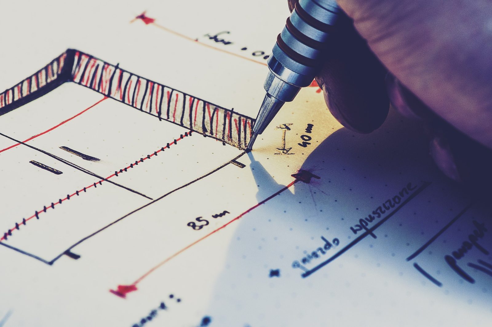
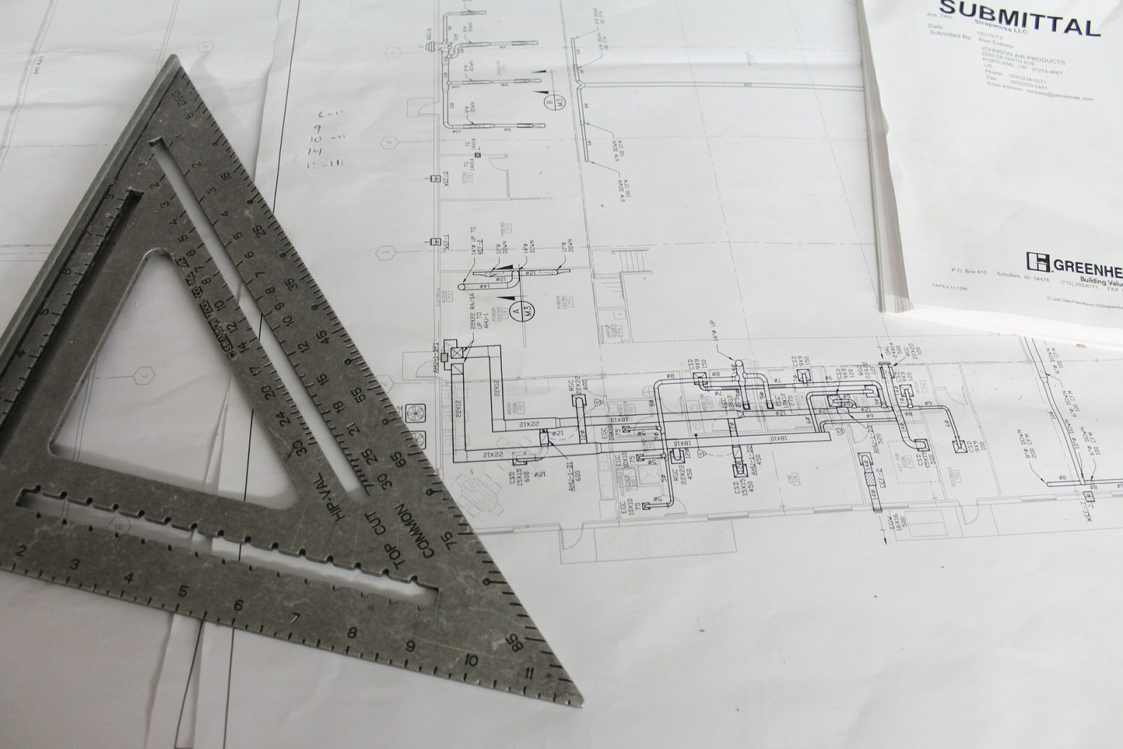
A construction drawing also called working drawings, blueprints of working drawings, in a nutshell, are a set of illustrations that show what is to be built much like a road map telling people where to go and where to turn. These drawings provide all the detailed information that’s both graphics (blueprint) and written (specifications) about the construction project at the uni tutor.
Read More at Touchless Car Wash
The construction drawings is also part of the legal document that forms the contract between the owner and the contractor.
A complete set of construction drawings for a construction project will usually compromise of floor plans, elevations, sections and detail drawings ( electrical, plumbing, etc.) that will piece together to provide a complete picture of the construction project. Construction drawings were and are still being prepared by hand today, but a lot are already being made using CAD ( Computer-aided Drawing/Drafting) software, and also using BIM ( Building Information Modelling).
Because these construction drawings are so important, they are usually are made in multiple copies just in case they get lost, but nowadays a drawing document management software helps companies in the organization of their construction drawings by storing and organizing it in a central repository system.
Architects and engineers spend many years in school to be able to draw one because it takes skill and technical knowledge to create one, and people who don’t have the proper training will have a very difficult time if ever they succeed in trying to make one. However, if you, for whatever reason find yourself in a position wherein you have to read a construction plan, you can, with some practice will be able to do so like a pro. Below are some basic things that you should remember:
- Relax, Focus on One Corner First
If you are looking at paper construction plans, keep in mind that it is big ( about 24 by 36 inches), and consists of several pages. To start reading these documents, make sure that you have a clear, dry workspace that you can unfold the plans keeping in mind that these plans are fragile and can easily tear and fade and can easily get damaged if they get wet. If this is not enough motivation to keep them dry, it might help to think that these plans are very expensive to make and cost hundreds of dollars to replace Moon Lamp.

If it’s your first time to look at this kind of construction plans, it’s normal to feel intimidated because of its size and the amount of detail so it really helps to relax and clear your mind. The first thing to do is focus your attention on one corner and work your way across. A well-executed plan shows lots of details and is highly accurate.
- Know the Basics
Familiarize Yourself With Common Blueprint Symbols
Construction plans have symbols that stand for components of the completed structure, and in complex projects, architects and engineers can use hundreds of abbreviation and symbols. These symbols represent all the structural components. The symbols are mostly standardized but sometimes architects use their
- Read the Cover Sheet
The cover sheet, as the name implies is the first page of the construction plan. The cover sheet will typically contain the following information: Project name and Location, Contents of the Set, Location Map, and Site Plan. The cover sheet is like a table of contents and will list the sheets contained within the drawings and the contents of each sheet. If needed, additional information can be added to the Cover sheet, depending on the construction project.
After the cover sheet is the plan index. Here it lists all the drawings contained in the set. It also contains a list of commonly used abbreviations, a scale bar, and design notes.
- Know Which Plans You Are Looking At
Construction plans are composed of several pages and typically the architect will identify each drawing with a letter and a number. It helps to be familiar with what these plans are.

Plumbing Plans Are Numbered Beginning with “P”
The plumbing drawing pages show the location and what type of plumbing are incorporated in the construction project. The plumbing plans usually contain 2 parts:
- The plumbing rough-in. This drawing sheet shows the location of the pipes which are to “stubbed up” so that plumbing fixtures can be connected to water supply, drain/waste, and vent systems.
- Plumbing floor plan. This sheet shows the location of the different types of plumbing fixtures as well as where the route pipes will be run for potable water, and drain, waste and vents.
The Site Plans Are The Sheets That Are Numbered Starting with The Letter C
The sites plan are the pages that are numbered ( usually on the lower right-hand side corner) starting with C. The site plans typically have the following information:
- The site topography – this indicates whether the construction site is flat, sloped etc.
- Demolition Plan. These sheets show which structures will be demolished on the site before grading for construction. Things that will not be destroyed are indicated in the keynote.
- Site Utility Plans. These sheets show the the exact location of existing underground utilities so that they can be left untouched during the excavation rim protector.
Structural Plans Are Numbered beginning with “S”
These plans include details for the following:
- Foundation plan. The foundation plan will basically show where all the nuts and bolts will go to.
- Footing schedule is usually located on the first sheet of the structural notes as well as information about reinforcing requirements, and other statements needed for structural strength and testing requirements.
- Framing Plans indicate what kind of materials will be used for framing the building – wood, steel, etc car scratch repair.
Architectural Plans are Numbered beginning with “A”
These sheets contain the measurement for the floor plans, elevations, building sections, wall sections and other information containing oriented views of the building design.
Mechanical Drawings are numbered Beginning with “M”
These sheets will show the location of what is collectively known as HVAC ( Heating, Ventilation, and Air Conditioning), ductwork, and refrigerant piping and control wiring.
These things that are mentioned here are just the tip of the iceberg when it comes to deciphering a construction drawing, but we hope that it’s enough for you to go on in your quest to successfully read a construction drawing. TuneUPTrends. If you need assistance with your technology, BCA IT in Miami is an IT support firm that services construction companies.


